Solar Inverter Fault & Error Codes Troubleshooting Guide (Fault 08, 09, Warning 04)
Technically Reviewed by Engr. Muhammad Naeem · Last Updated: 2026
Key Takeaway (AEO Direct Answer)
Common solar inverter faults in Pakistan include Fault 08 (bus overvoltage caused by winter cold Voc rise), Fault 09 (internal IGBT bus soft-start failure), Warning 04 (BMS communication loss between battery and inverter), and Grid Overvoltage (tripping above 253V AC on shared suburban distribution transformers).
1. Diagnostic Fundamentals for Solar Inverters in Pakistan
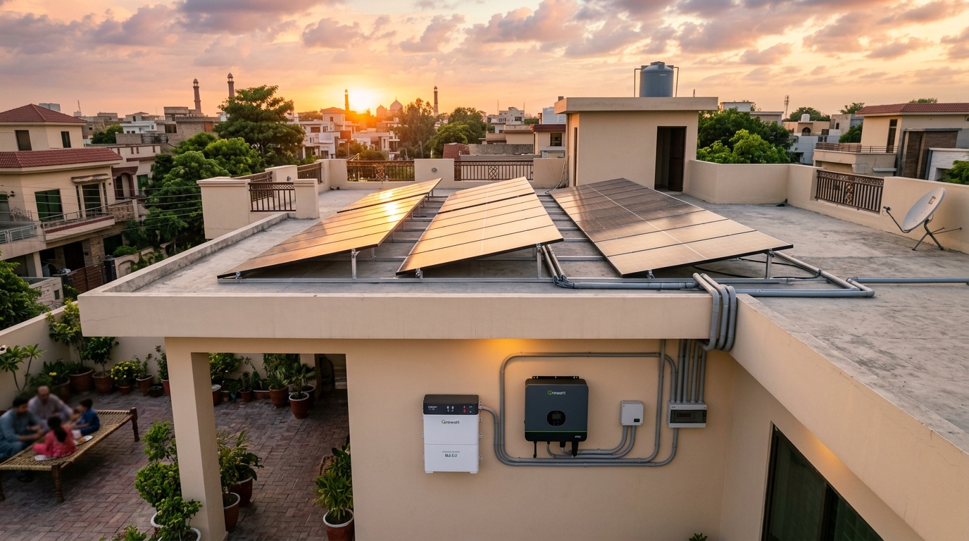
Solar inverters deployed in Pakistan operate under some of the harshest electrical and environmental conditions on earth. Between violent grid surges, localized brownouts (where utility voltage drops below 160V AC), excessive dust infiltration, and ambient temperatures swinging from near-freezing in winter to 48°C in summer, inverters frequently display error codes, warning indicators, or trigger protective shutdowns.
Understanding whether an error code indicates an external grid aberration, an improper field wiring configuration, a communication timeout, or a fatal internal component breakdown prevents premature equipment replacement and unnecessary repair expenses. Below is an exhaustive engineering diagnostic manual covering major residential and commercial inverter platforms operating in Pakistan (including Growatt, Inverex Nitrox/Veyron, GoodWe, Solis, Knox, and Fronus).
2. Master Troubleshooting Matrix: Common Fault Codes
The table below summarizes the most critical operational fault codes encountered across Pakistani residential installations, their underlying root causes, and verified engineering remediation steps.
| Code / Error | Description | Underlying Root Cause | Engineering Action & Fix |
|---|---|---|---|
| Fault 08 | DC Bus Overvoltage | Cold weather Voc voltage expansion exceeding inverter maximum MPPT limit. | Reconfigure string sizing; remove 1 panel per string to lower cold Voc. |
| Fault 09 | Bus Soft Start Failure | Internal charging resistor damaged or shorted IGBT power transistor. | Requires authorized distributor service center repair/replacement. |
| Warning 04 | Battery Low / BMS Loss | CAN/RS485 communication loss between Lithium BMS and inverter controller. | Check RJ45 pinout mapping; verify baud rate setting (9600 vs 115200). |
| Fault 51 | Overcurrent / Surge | Large motor inductive inrush current exceeding inverter peak surge capacity. | Install soft starter on 1.5HP+ water pumps or stagger AC start times. |
| OV-V / 253V+ | Grid Overvoltage | Neighborhood transformer voltage rise due to massive simultaneous solar export. | Activate Volt-VAr Q(U) control; increase AC cable gauge; request DISCO tap drop. |
| Fault 58 | Output Voltage Low | Severe load short-circuit or loose neutral terminal on distribution board. | Inspect AC distribution board neutral busbar; test circuit insulation. |
3. Deep-Dive: Cold Weather Voc Rise and Fault 08 Remediation
Fault 08 (DC Bus Overvoltage) occurs overwhelmingly between December and February across northern and central Pakistan (Islamabad, Rawalpindi, Lahore, Peshawar). Installers frequently design panel strings based strictly on the module's nameplate Open Circuit Voltage (Voc) rated at 25°C Standard Test Conditions (STC).
However, photovoltaic semiconductor physics dictate that voltage rises as temperature drops. The temperature coefficient of open circuit voltage (βVoc) for modern N-Type panels is approximately -0.25%/°C. When ambient temperatures in Punjab drop to 3°C on a crisp December morning, the effective panel Voc rises by approximately 5.5%.
If an installer placed twenty 585W panels (Voc = 51.5V) in a single series string, the nominal voltage is 1,030V at 25°C. At 3°C, the actual string voltage surges to 1,086V DC! This immediately breaches the inverter's maximum DC input threshold (typically 1,000V or 1,050V), forcing the inverter to lock down into Fault 08 to prevent explosive destruction of the internal high-voltage DC bus capacitors. The permanent solution is calculating maximum string sizing based on minimum historical localized temperature, ensuring string Voc at 0°C never exceeds 900V DC on a 1,000V machine.
4. Warning 04 & BMS Communication Timeout Troubleshooting
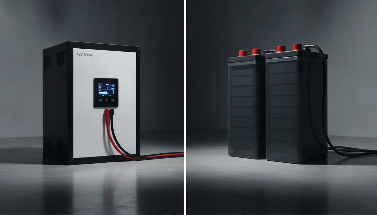
In modern hybrid solar systems equipped with Lithium Iron Phosphate (LiFePO4) battery packs, Warning 04 indicates a communication breakdown between the inverter's internal battery management protocol and the external battery BMS. When communication drops, the inverter defaults into a protective low-current charging mode or disconnects the battery entirely.
- RJ45 Cable Pinout Mismatch: Inverters (such as GoodWe, Inverex, and Deye) use specific pin assignments for Controller Area Network (CAN) and RS485 communication. For instance, CAN-High is typically assigned to Pin 4 and CAN-Low to Pin 5. Standard computer ethernet cables often utilize different twisted pair shielding. Verify that your communication cable matches the exact manufacturer pinout diagram.
- BMS Protocol Selection: In the inverter's battery settings menu, ensure the selected battery protocol matches the battery manufacturer (e.g., Pylontech, Pace, Narada, or Shoto). Selecting an incorrect protocol ID prevents handshake synchronization.
- Baud Rate Verification: Verify whether the battery BMS communication DIP switches are configured for 9600 bps or 115,200 bps matching the inverter's hardware specification.
5. Standard Operating Procedure: Safe Manual Reset Protocol
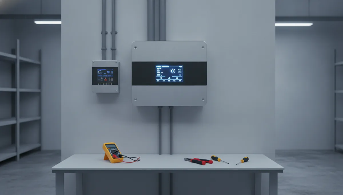
When an inverter enters a latched fault state, amateur technicians often cycle power randomly, which can arc internal DC contactors and damage sensitive microprocessors. Always execute this strict, step-by-step shutdown and reset protocol:
- Step 1: Disconnect AC Breakers: Turn off the AC Output breaker (home load) followed by the AC Grid Input breaker on the distribution panel. This eliminates all load current flowing through the inverter.
- Step 2: Turn Off DC PV Isolator: Rotate the rotary DC isolator switch on the underside of the inverter to the "OFF" position, disconnecting high-voltage solar panel strings.
- Step 3: Disconnect Battery Circuit: Turn off the DC battery MCCB breaker or pull the inline DC fuses connecting the battery bank to the inverter.
- Step 4: Discharge Internal Capacitors: Wait at least 5 to 7 full minutes. High-voltage electrolytic capacitors inside the inverter require several minutes to safely bleed off stored energy via internal discharge resistors. The LCD screen will turn completely blank.
- Step 5: Sequential Re-Energization: Reconnect the battery breaker first (allowing the inverter controller to boot and identify system voltage), followed by the DC solar PV isolator. Once the inverter screen stabilizes and reports normal solar voltage, turn on the AC Grid Input breaker and finally the AC Output load breaker.
Prevent Inverter Tripping: Verify your string voltage design using our Solar Load Calculator, explore certified Tier-1 hybrid hardware in our Inverters Catalog, or request professional diagnostic assistance through our Instant Quotation Tool.
Frequently Asked Questions: Inverter Fault Codes in Pakistan (2026)
What does Fault 08 mean on a solar inverter in winter?
Fault 08 indicates DC Bus Overvoltage. During cold winter mornings, solar panel open circuit voltage (Voc) expands naturally. If too many panels are wired in series, total string voltage exceeds the inverter's maximum input threshold, triggering protective shutdown.
Can Fault 09 be repaired on-site by a local electrician?
No, Fault 09 typically signifies an internal bus soft-start resistor failure or damaged IGBT switching transistors. Attempting field repairs voids the manufacturer warranty; the inverter must be serviced at an authorized distributor warranty center.
How do I fix Warning 04 on a hybrid inverter with a lithium battery?
Warning 04 indicates lost communication between the battery BMS and inverter. Check the RJ45 communication cable pinout (CAN vs RS485), ensure correct battery protocol selection in the inverter menu, and verify matching communication baud rates.
Why does my inverter trip with an overvoltage error around 1:00 PM?
Midday grid tripping occurs when high solar export from multiple neighborhood systems pushes localized distribution grid voltage above 253V AC. Upgrading AC cables, activating Volt-VAr control, or requesting a DISCO transformer tap adjustment resolves this issue.
How long should I wait before turning an inverter back on after shutdown?
Always wait 5 to 7 full minutes after disconnecting all power sources before turning an inverter back on. This allows internal high-voltage electrolytic capacitors to safely bleed off stored charge completely.
Disclaimer: High-voltage DC circuits carry severe risk of electric shock and arc flash. Never open internal inverter casings or manipulate live cabling. Consult certified TechnoKraft engineering personnel for professional diagnostic assistance.
Calculate Your Solar Cost — Right Here
Enter your monthly bill to get an instant estimate